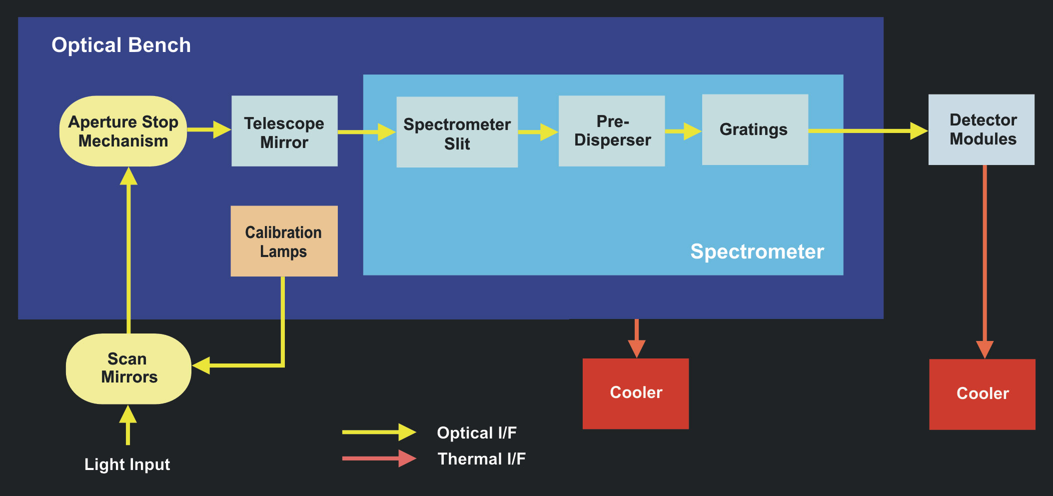
| Fig. 3-1 | General spectrometer
layout illustrating SCIAMACHY's main components (Courtesy: DLR-IMF) |
|
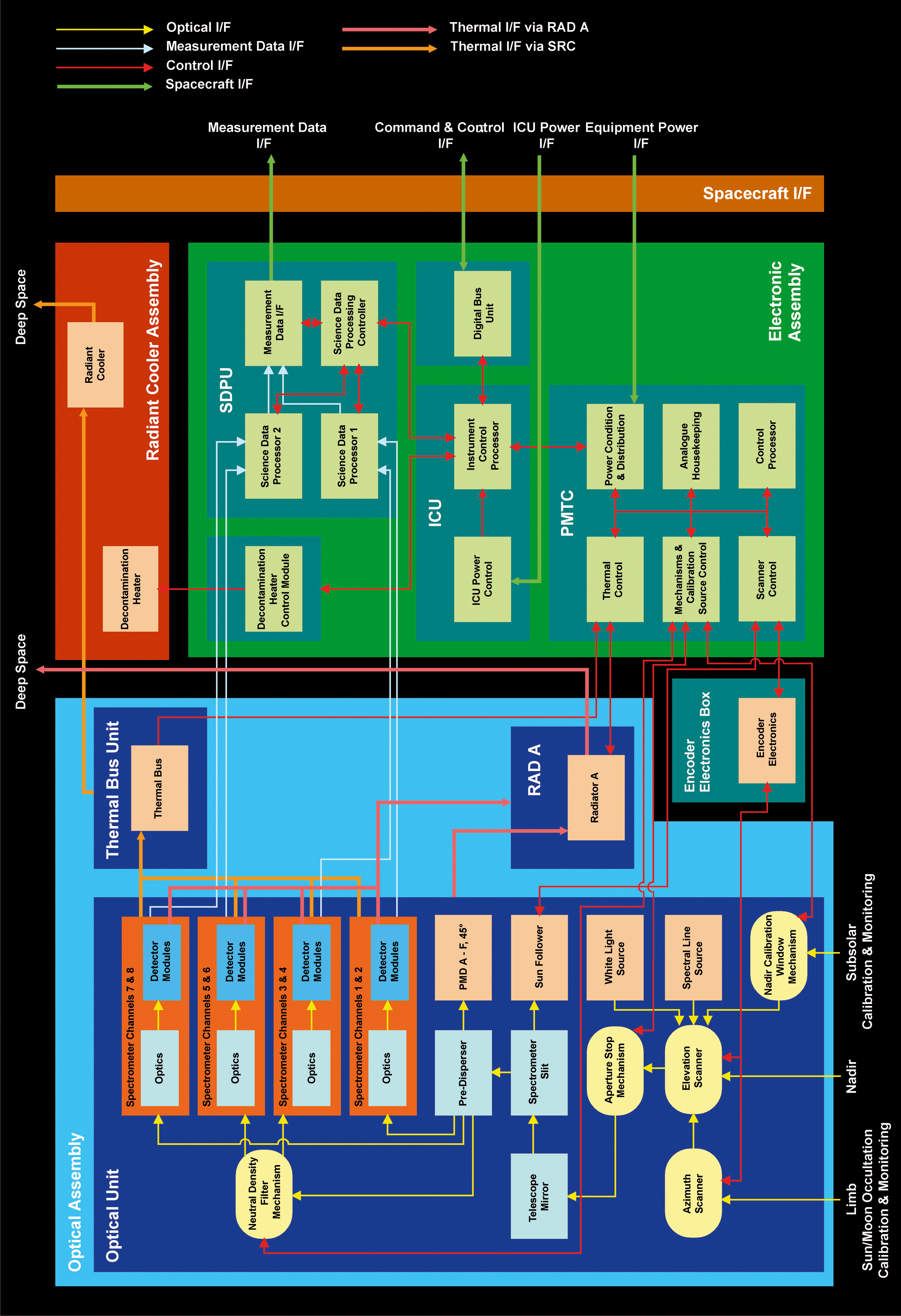
| Fig. 3-2 |
SCIAMACHY functional block diagram with simplified interfaces between assemblies and modules.
(Courtesy: DLR-IMF; adapted from EADS Astrium 2004) |
|
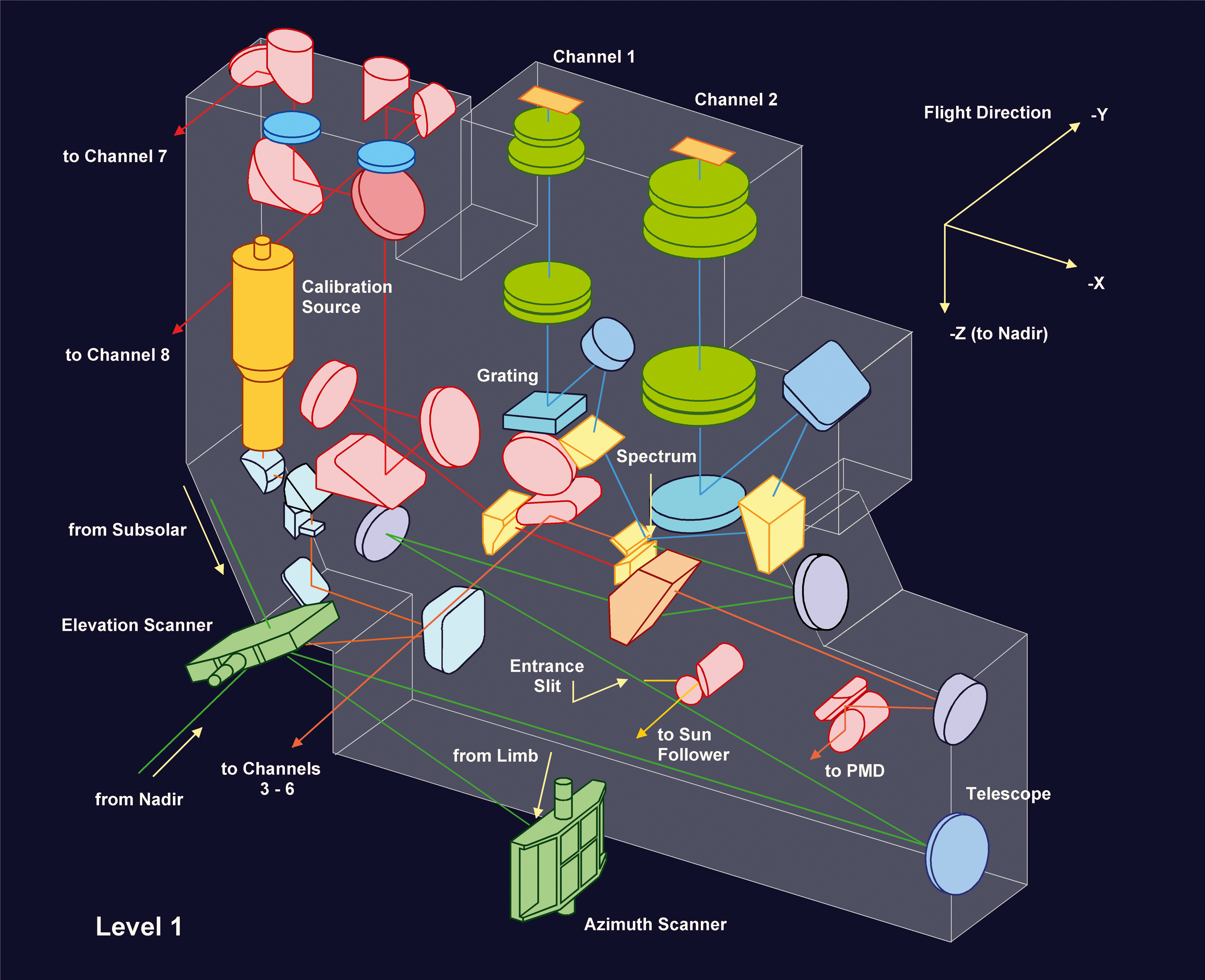
| Fig. 3-3 |
Optical configuration level 1. (Courtesy: DLR-IMF; adapted from SJT 1996) |
|
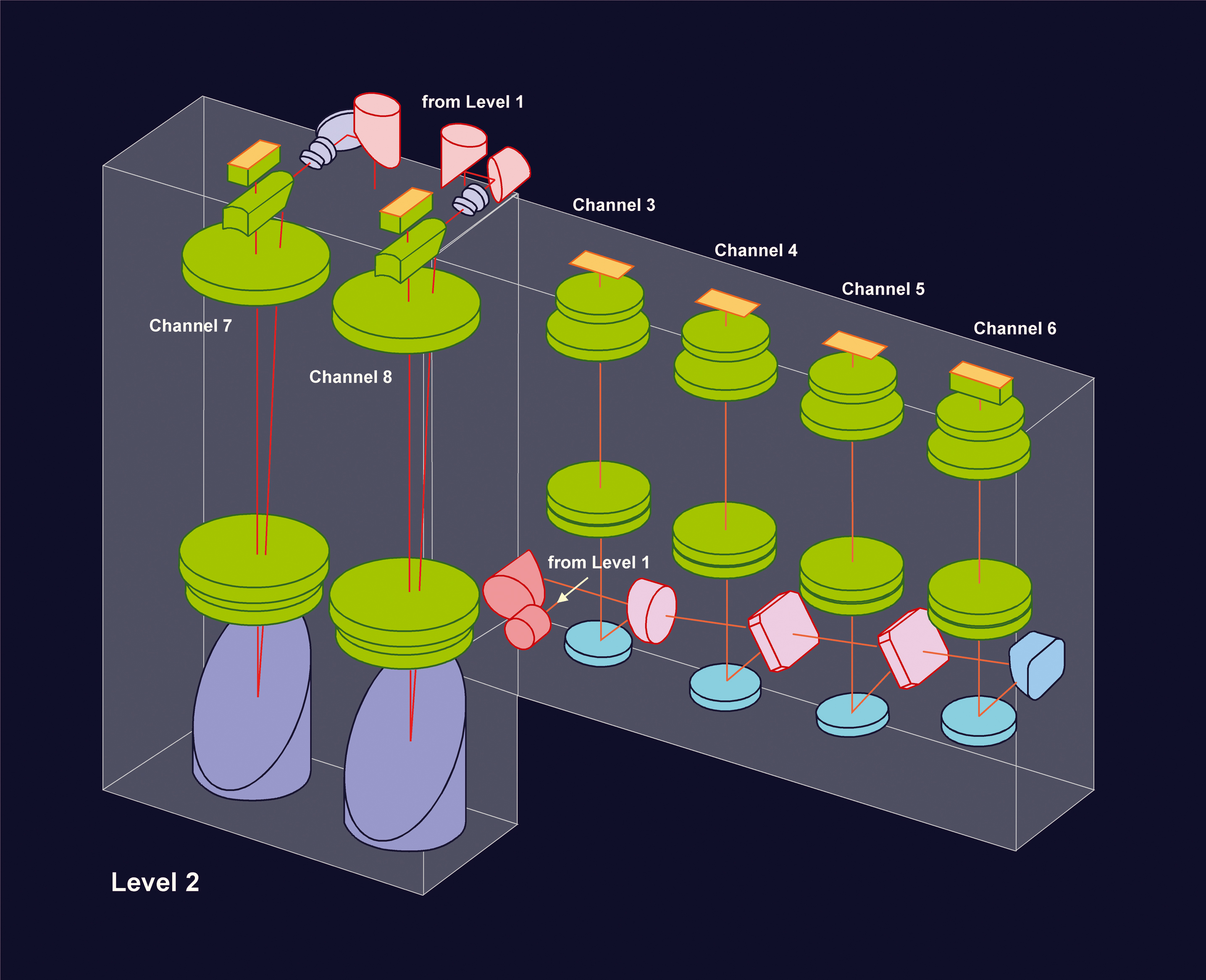
| Fig. 3-4 | Optical configuration level 2.
Courtesy: DLR-IMF; adapted from SJT 1996) |
|
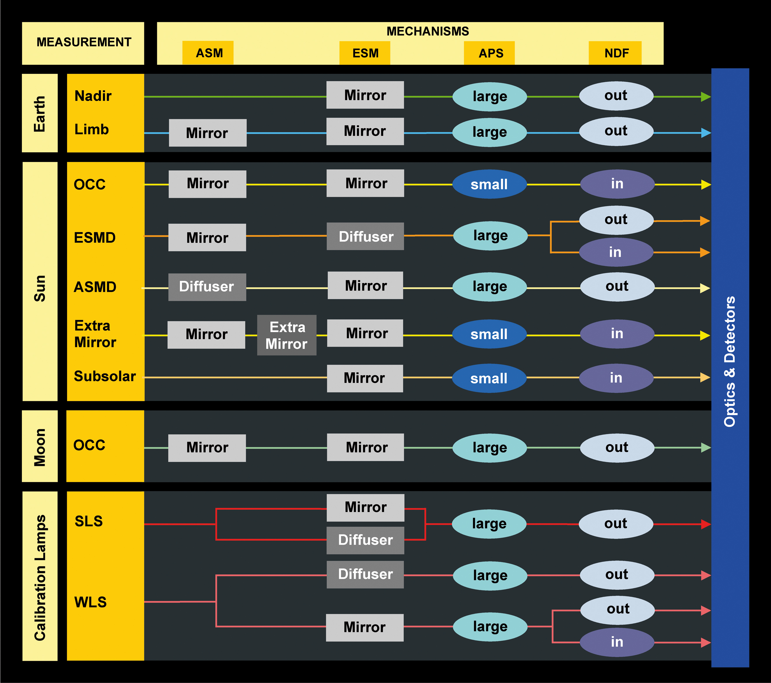
| Fig. 3-5 |
SCIAMACHY optical 'trains'. Each 'train' defines a path for the measured light through the instrument to the detectors.
Light sources can be external or internal. (Courtesy: DLR-IMF/SRON) |
|
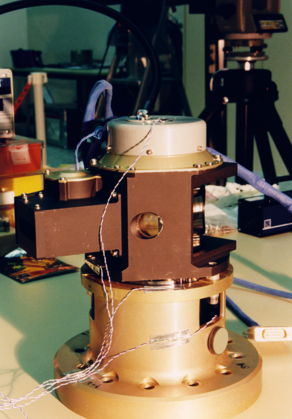
| Fig. 3-6 |
ESM on vibration test adaptor. The leftmost rectangular opening is the Nadir Calibration Window.
(Photo: EADS Astrium) |
|
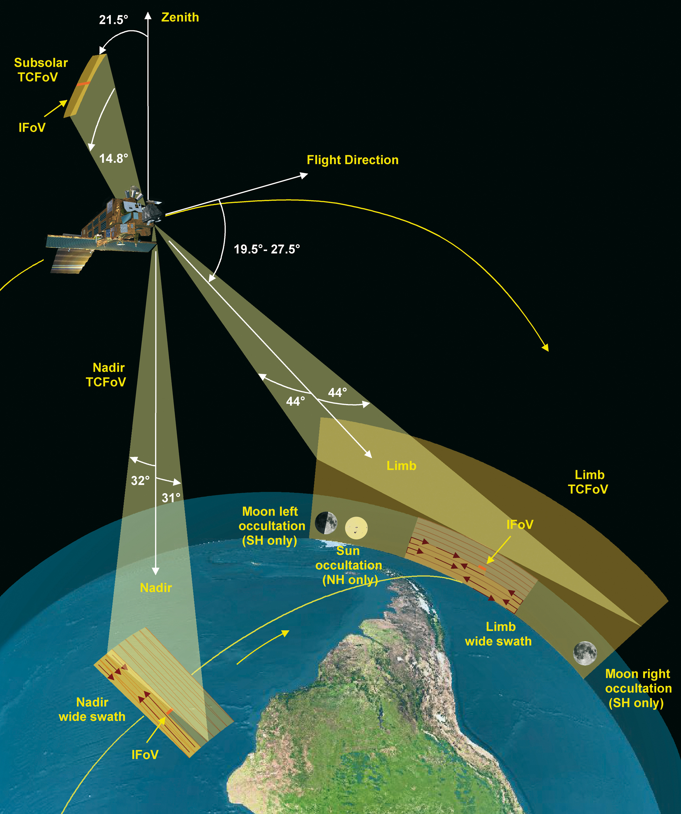
| Fig. 3-7 |
Sketch of SCIAMACHY's TCFoV and observation geometries. (Courtesy: DLR-IMF) |
|
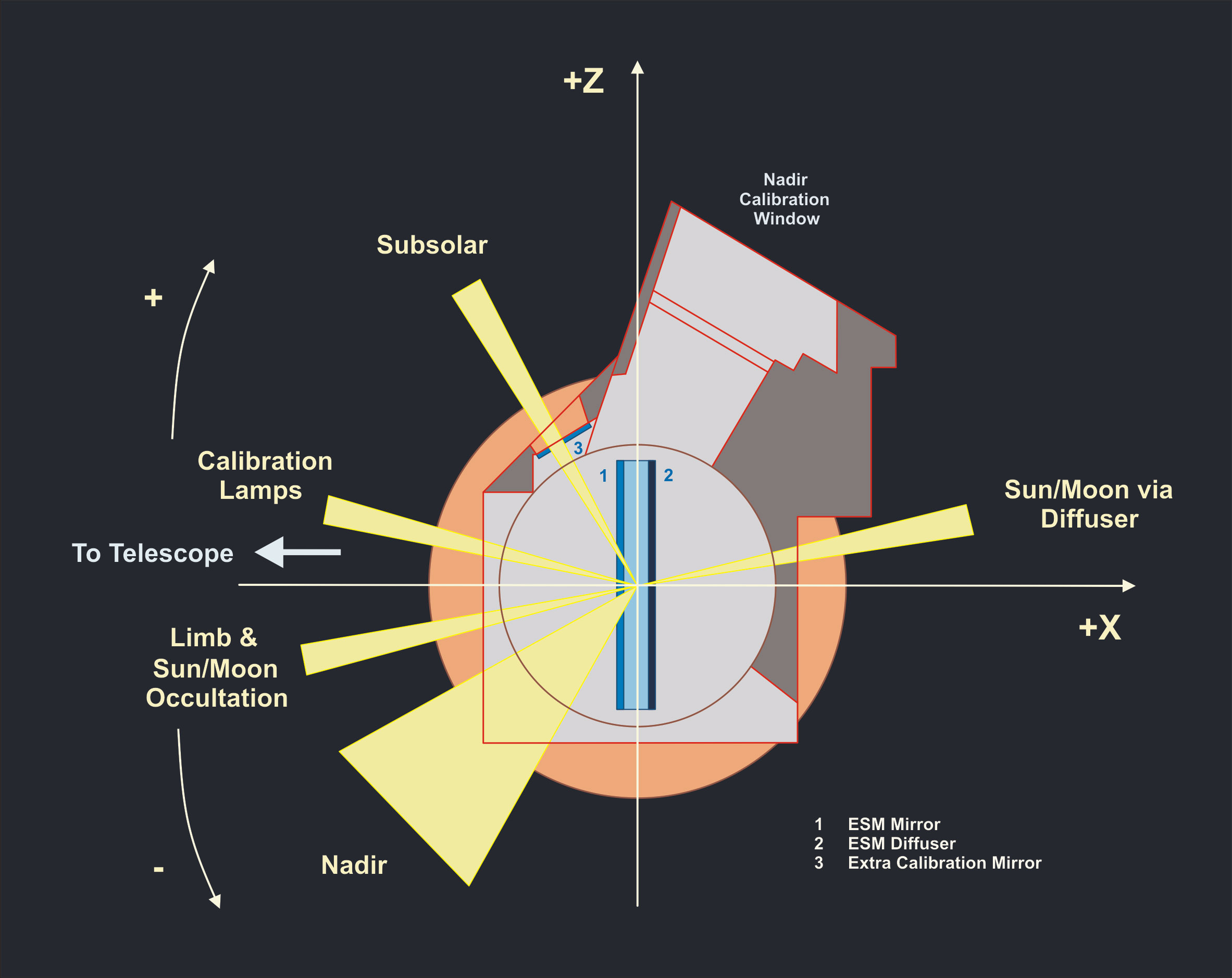
| Fig. 3-8 |
ESM mirror's normal during specified observing geometries. (Courtesy: DLR-IMF) |
|
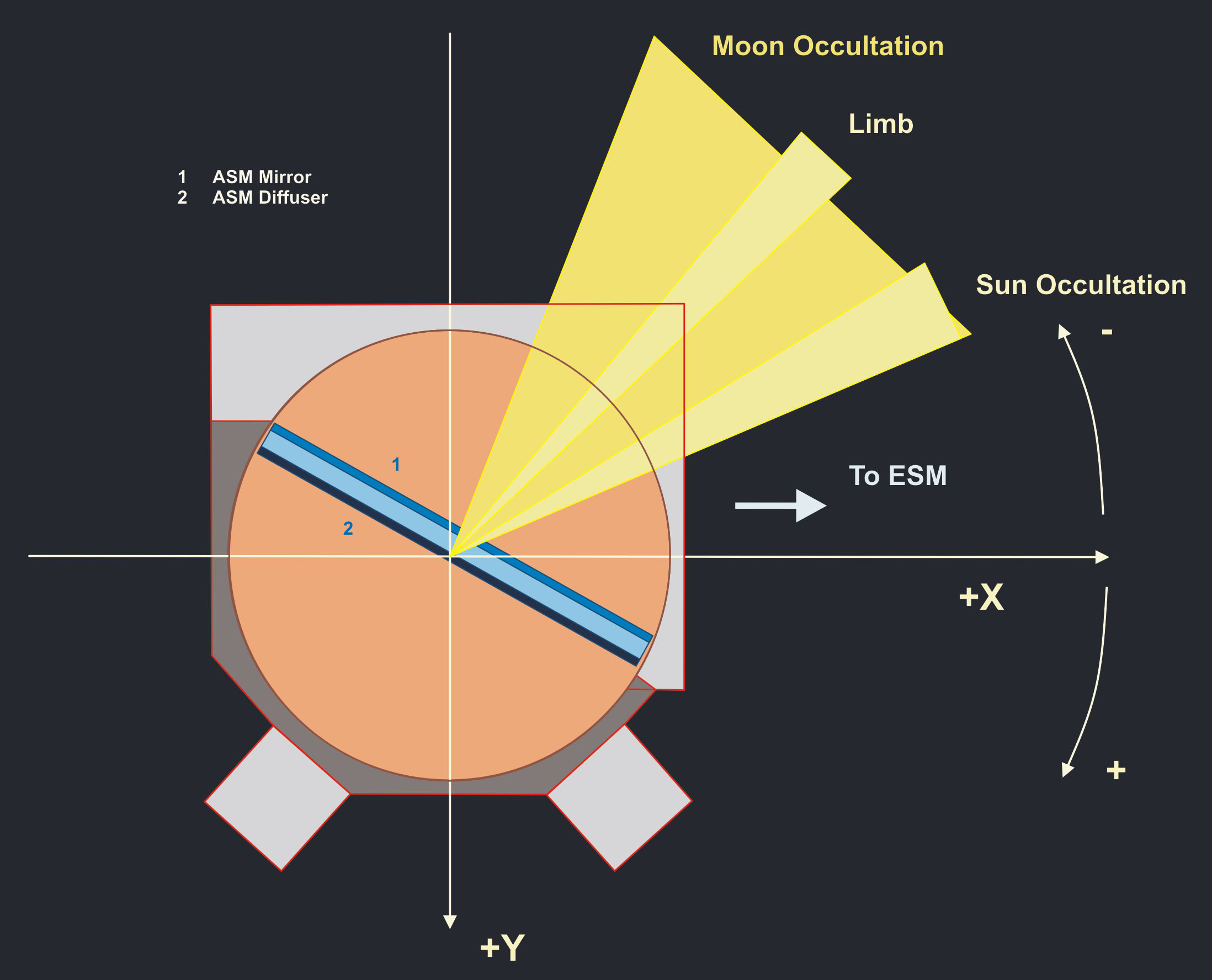
| Fig. 3-9 |
Same as Fig. 3-8 but for the ASM. (Courtesy: DLR-IMF) |
|
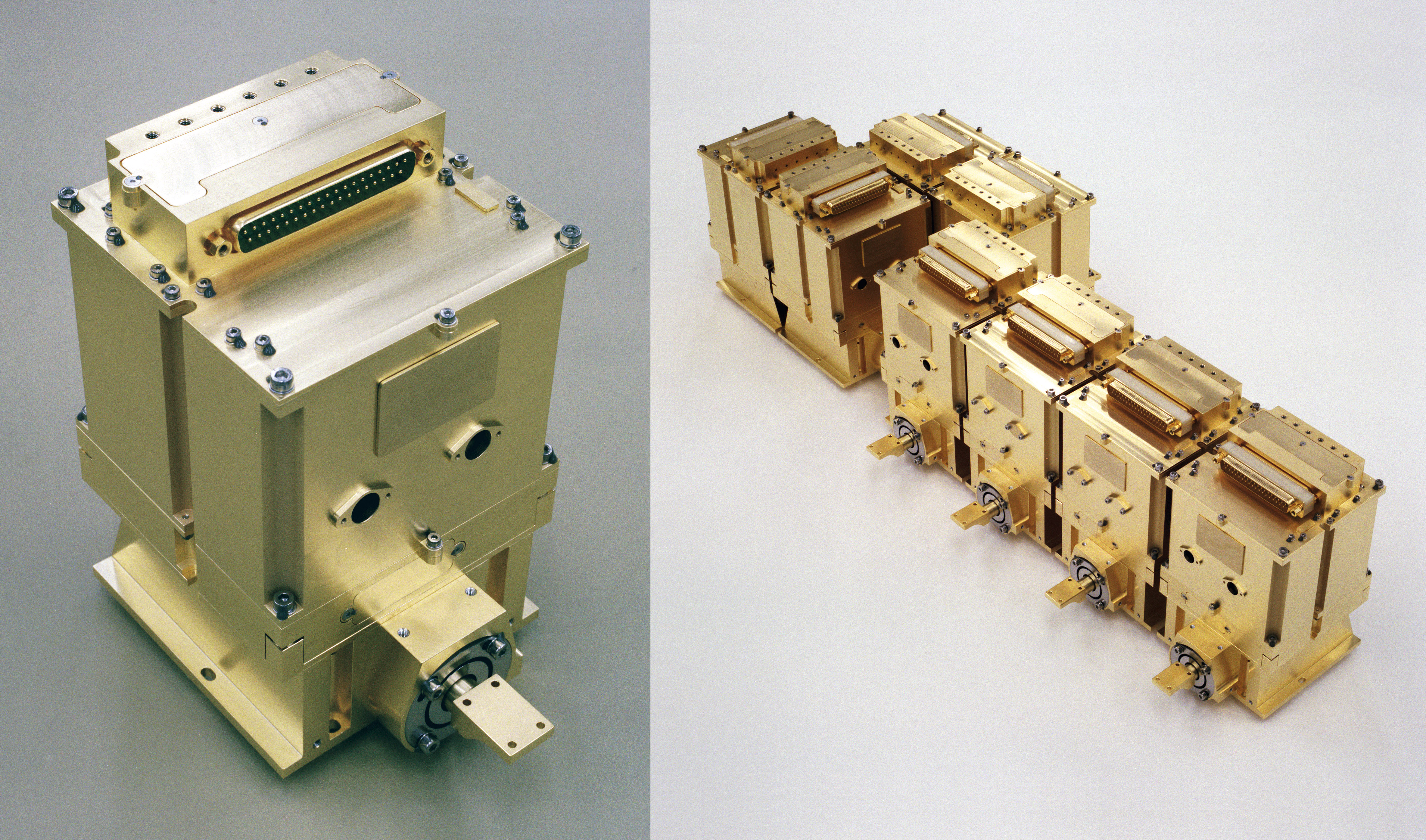
| Fig. 3-10 |
Single SCIAMACHY
detector module (left) and the full complement of 8 detector modules (right).
(Photo: SRON) |
|
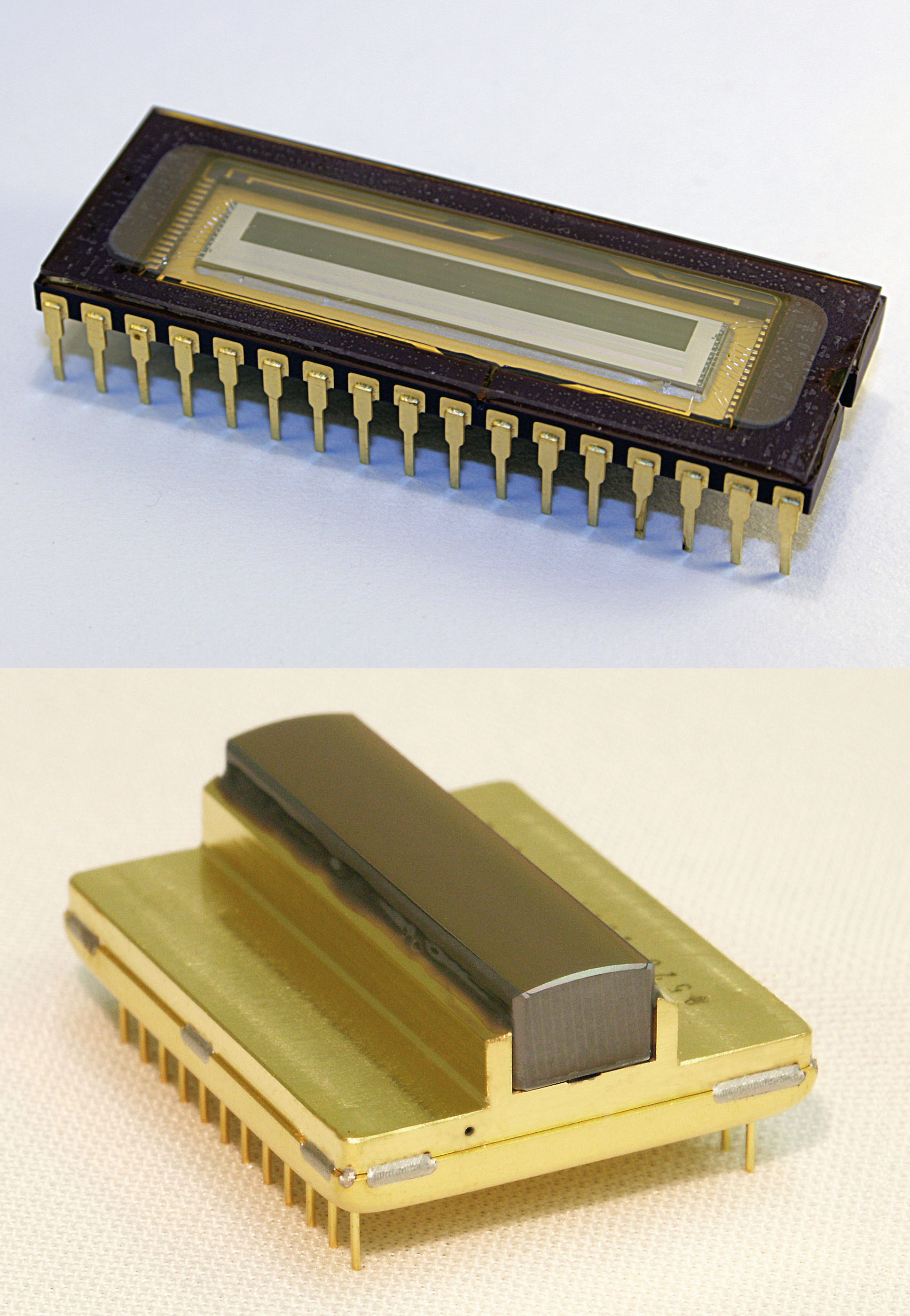
| Fig. 3-11 |
The RETICON (top) and EPITAXX (bottom) linear detector arrays. (Photo: SRON) |
|
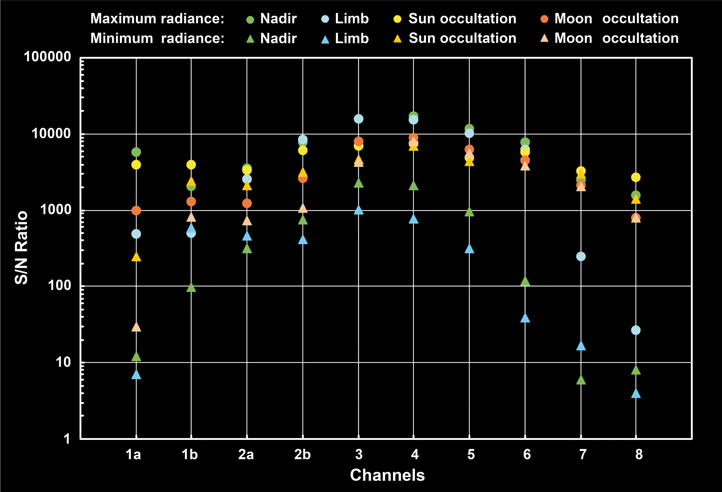
| Fig. 3-12 |
The signal-to-noise ratios for all channels as obtained during OPTEC-5 tests. The ratios were determined for minimum
and maximum radiance signals. (Courtesy: DLR-IMF) |
|
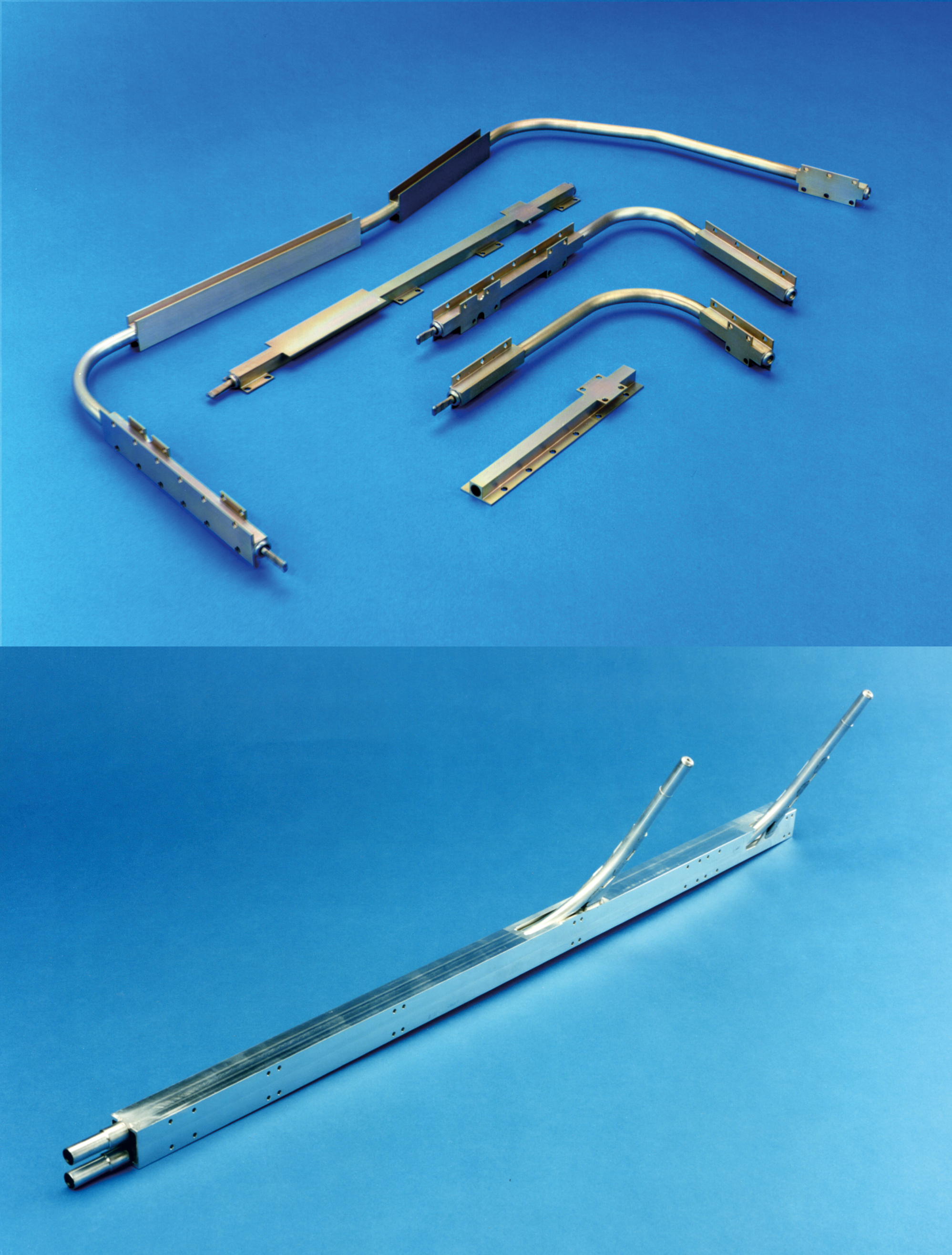
| Fig. 3-13 |
Heat pipes from the optical bench to RAD A (top) and cryogenic heat pipes from detector modules
7 and 8 to the SRC (bottom). (Photo: EADS Astrium) |
|
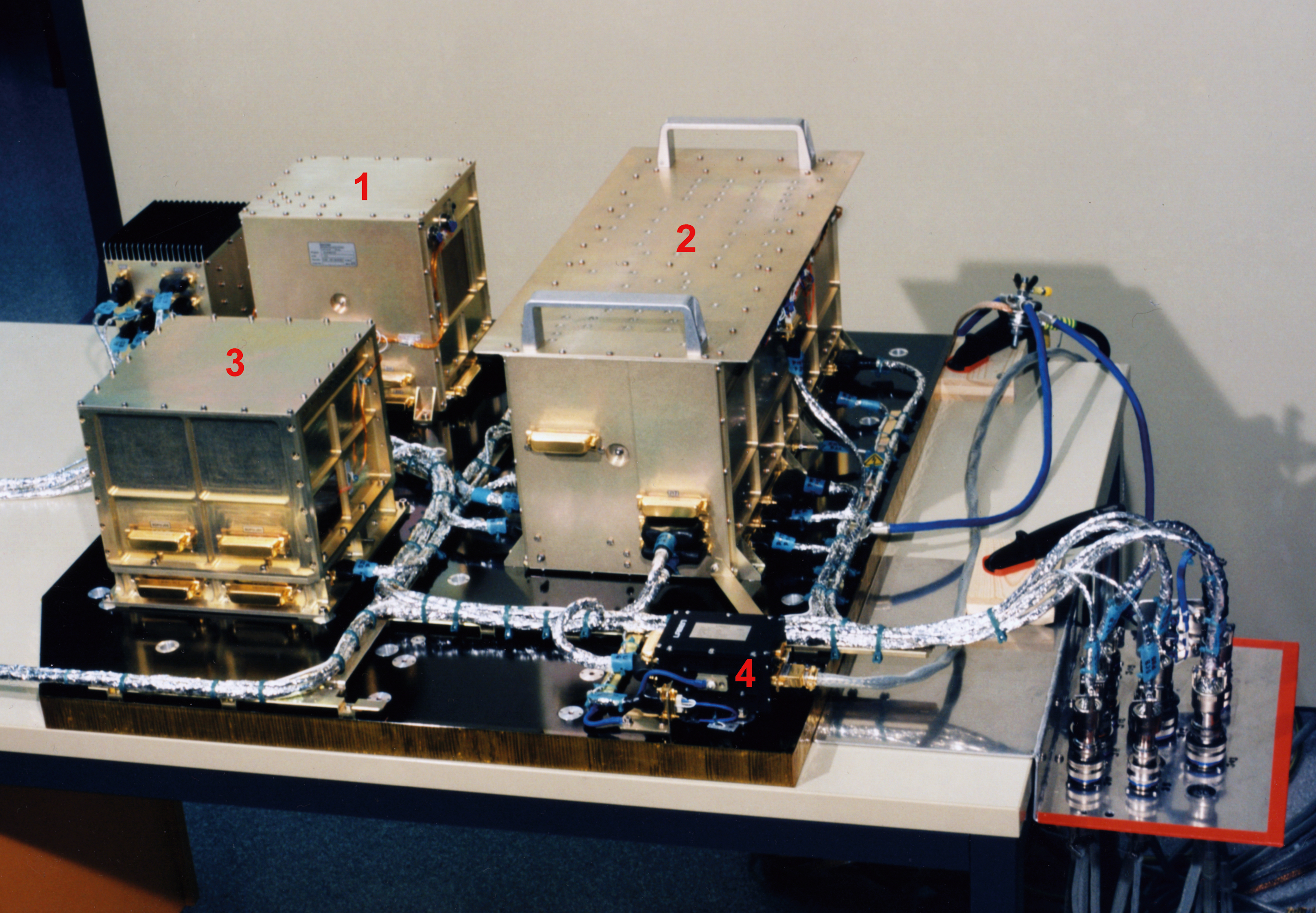
| Fig. 3-14 |
The Simplified Engineering Model of the EA with ICU (1), PMTC (2), SDPU (3) and DBU (4).
(Photo: EADS Astrium) |
|
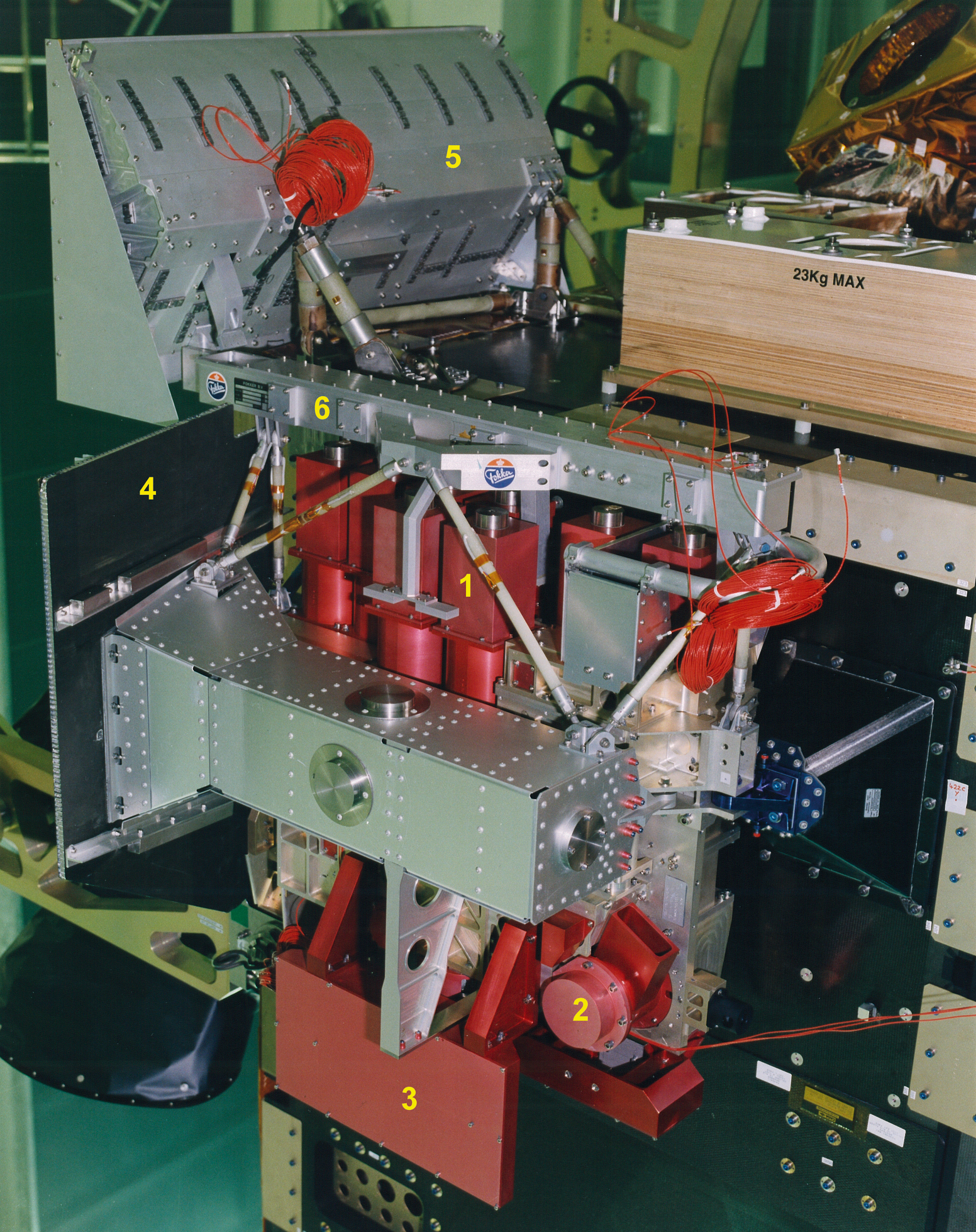
| Fig. 3-15 |
Structural Model of the OA showing the SCIAMACHY design with detector modules (1), ESM with Nadir Calibration Window (2),
limb baffle with cover (3), RAD A (4), SRC (5) and Thermal Bus (6). (Photo: ESA) |
|
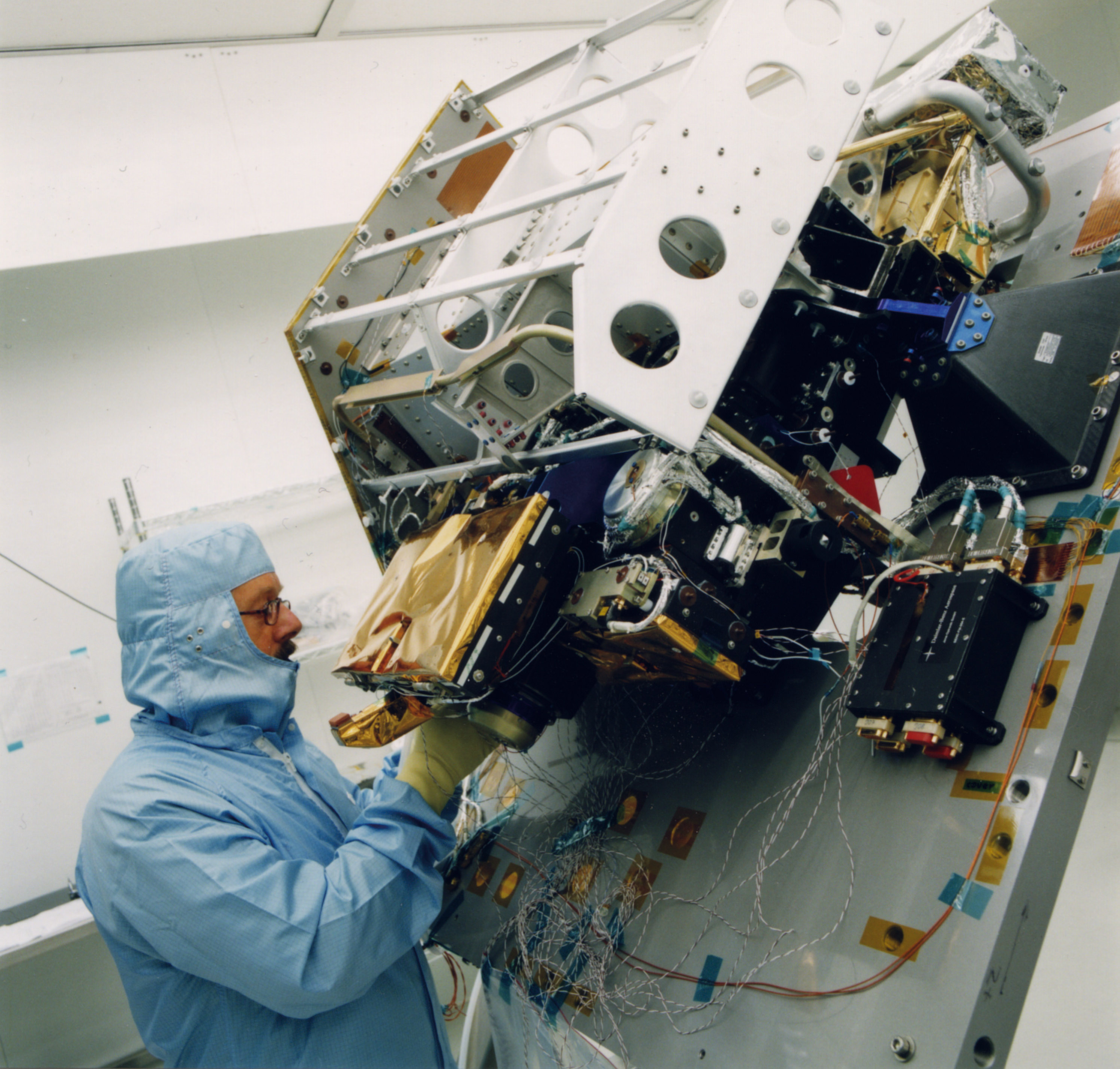
| Fig. 3-16 |
Integration of the OA. (Photo: Dutch Space) |
|
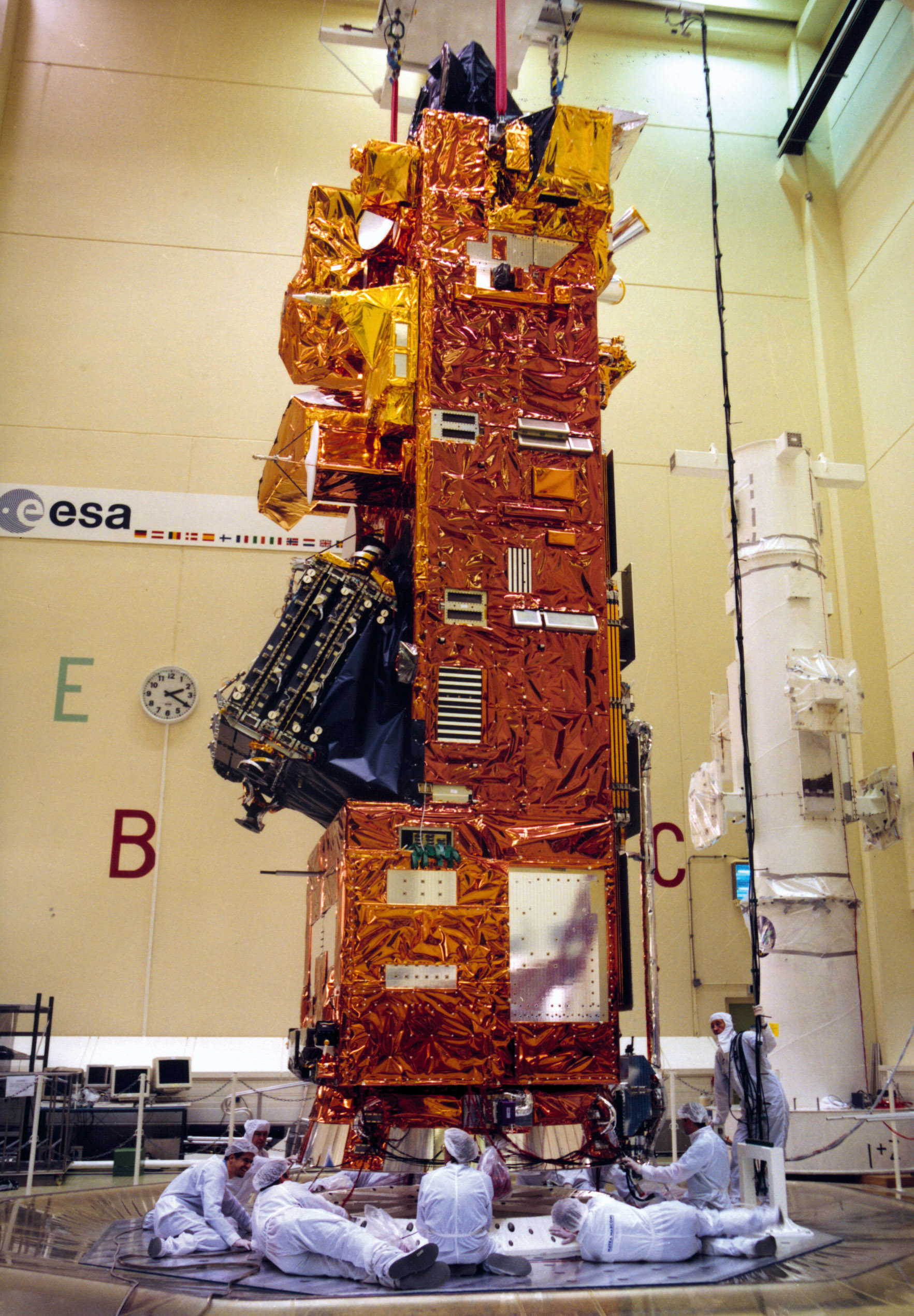
| Fig. 3-17 |
ENVISAT integration on the ESTEC Hydra vibration test facility. The instruments are covered with MLI. SCIAMACHY is the only
instrument located on the front panel (top right corner). (Photo: ESA) |
|
Page generated 31 August 2011