Measurement Parameter Description
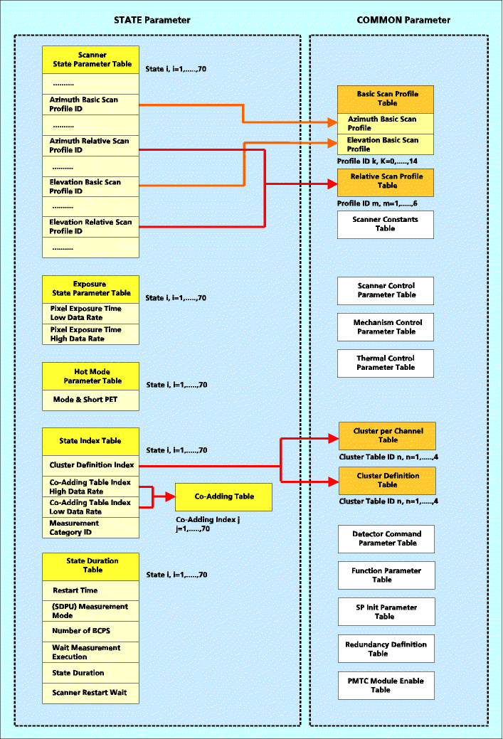
Each instrument state is defined by a series of individual measurement parameters, which can be grouped into STATE and COMMON parameter tables. A table summary can be found in the figure below.
SCIAMACHY instrument states: STATE and COMMON parameter tables |
The web pages provide information on
the content of all STATE parameter tables and those COMMON parameter
tables which are 'referenced' by STATE parameter tables.
Each table description includes
The list of tables is composed of
The Measurement Parameter tables do exist in two versions: The EEPROM version which represents the tables burnt into the EEPROM and the RAM version, which includes the EEPROM version plus all parameter modifications via ERCORMS at ICU initialisation. It is the RAM version which is actually used in-flight. The parameter tables provided on the web-sites are those for routine operations (final flight state configuration).
Note: The tables presented here are for information purposes only. If configuration controlled information is required for command & control, mission planning or data processing purposes the only applicable sources are the relevant documents (e.g. IOM).
This table defines the parameters for the Basic Scan Profile. Only one table of this class exists.
Table Template:
MCMD: | SET SCANNER BASIC PROFILES |
Columns: Basic Scan Profile Identifier: Basic Scan Position Azimuth: Basic Scan Rate Azimuth: Basic Scan Position Elevation: Basic Scan Rate Elevation: |
identifier of Basic Scan profile; range = 0–14 definition of the scanner azimuth start position of a basic scan profile in mrad; range = -6283185 to 6283185 (-2p to 2p) definition of the scanner azimuth scan rate in µrad/sec; range = -32768 to 32767 (-0.032768 to +0.032767 rad/sec) definition of the scanner elevation start position of a basic scan profile in µrad; range = -6283185 to 6283185 (-2p to 2p) definition of the scanner elevation scan rate in µrad/sec; range = -32768 to 32767 (-0.032768 to +0.032767 rad/sec) |
This table defines the clustering scheme. A total of four tables of
this class exist, corresponding to the
number of different clusterings.
Table Template:
MCMD: | SET CLUSTER DEFINITIONS |
Rows: Channel: Cluster Index: Cluster Identifier: Start Pixel: Length: |
identifier of the channel; range = 1a–8 (channels 1 and 2 are subdivided into 2 separate channels) identifier of the cluster; range = 1–64 (maximum) identifier of a cluster within a particular channel, i.e. channel cluster counter; range = 0–15 definition of the start pixel of a cluster; range = 0–8191 note that the numbering is continuous through all channels definition of the number of pixels contained in a cluster; range = 1–1024 |
This table provides supporting information for the definition of the
clusters. For each cluster definition
(indicated at top of each table), the clustering within all 8 channels is given.
Table Template:
Upper section: Columns:Channel ID: Channel - Start Pixel: Channel - End Pixel: Channel - Length: Channel Wavelength - Min: Channel Wavelength - Max: Lower section: Columns:Cluster ID: Cluster - Start Pixel: Cluster - End Pixel: Cluster - Length: Channel Wavelength - Min: Channel Wavelength - Max: Description: Cluster Index: Cluster Identifier: Start Pixel: Length: |
identifier of the channel; range = 1a–8 identifier of the first used pixel in the channel (excluding blinded pixels); range = 0–1023 identifier of the last used pixel in the channel (excluding blinded pixels); range = 0–1023 number of used pixels in the channel (End Pixels-Start Pixel+1) Start Pixel expressed in nm End Pixel expressed in nm
identifier of the cluster within the channel (including clusters with unused and blinded pixels); range= 0–15 identifier of the first pixel in the cluster identifier of the last pixel in the cluster number of pixels in the cluster (End Pixels-Start Pixel+1) Start Pixel expressed in nm (only for clusters with used pixels) End Pixel expressed in nm (only for clusters with used pixels) characterisation of unused and blinded pixels, virtual channels, overlaps and major measurement targets (AE = aerosols) identifier of the cluster; range = 1–64 (maximum) same as ‘Cluster ID’ same as ‘Cluster - Start Pixel’ same as ‘Cluster - Length’ |
This table defines the number of clusters in each channel. Only one table of this class exists.
Table Template:
MCMD: | SET CLUSTERS PER CHANNEL |
Columns: Cluster Table ID: Channel 1 – Channel 8: |
identifier of the corresponding Cluster Table Index; range = 1–4 number of clusters within the particular detector channel; range = 1a–8 |
A Co-Adding table exists for each co-adding index, i.e. the total number of tables in this class is 70
(the equality of the number of co-adding tables and the number of states is
only accidental).
Each Co-Adding table stores consecutively 64 co-adding factors.
Table Template:
MCMD: | SET CO-ADDING TABLE |
Rows: Cluster Index: Co-Adding Factor: |
identifier of the cluster; range = 1–64 (maximum) number of co-addings to be applied to the pixel data in a cluster; range = 1–64 (maximum) 1 = no co-adding applied n, 1 < n < equal 64 (n data words will be co-added) |
This table defines the integration times in seconds as a function of cluster index. The table is not stored onboard but has been derived from State Index, Co-adding, PET and Cluster Definition table (integration_time = co-adding � PET). For Sun occultation states the high data rate settings of Cluster Definition Index and PET have been used; for all other states the low data rate settings.
Table Template:
Rows: Cluster Index: Co-Adding Factor: |
identifier of the cluster; range = 1–64 (maximum) integration time in seconds; derived from PET � Co-adding factor (for clusters in Hot Mode the effective integration time is given) |
The table Detector Cmd Words defines the parameters for the non state
dependent settings of the 8 detector channels.
The table is set by the identical MCMD as the DME ENABLE list. Only
one table of this class exists.
Table Template:
MCMD: | SET DETECTOR COMMAND WORDS |
Header Line:
Columns: DME DEC: Exp. Time Factor: Mode BIN: Section Address DEC: Ratio BIN: Control BIN: Comp Mode BIN: Fine Bias Setting BIN: Short PET BIN: |
spans the area of information for the Detector Cmd Word
ID of the detector module electronics parameter not delivered from this table to the SDPU defines the operational mode. Set to default value ‘00’. Range: 00 – 01 channel 1 – 5 … normal mode channel 6 – 8 … state dependent defined by MCMD - SET HOT MODE defines the intersection of the 2 virtual channels of a detector applies to channel 1 – 5 only Range: 1 – 511;‘0’ used if no virtual channels are defined parameter not delivered from this table to the SDPU. Set to default value ‘00001’. applies to channel 1 – 5 only parameter not delivered from this table to the SDPU. Set to default value ‘01’. defines the setting of the ‘Offset’ compensation. applies to channel 6 – 8 only Range: 00 – 11 adjusts the setting of the ‘Bias’ voltage. applies to channel 6 – 8 only Range: 000 – 111 defines PET in HOT MODR ( not delivered from this table to the SDPU) applies to channel 6 – 8 only |
The table DME ENABLE list defines if one of the 8 detector channels is enabled/disabled. The table is
set by the identical MCMD as the Detector Cmd Words table. Only one table of this class exists.
Table Template:
MCMD: | SET DETECTOR COMMAND WORDS |
Columns: DME DEC: Enabled/Disabled BIN: |
identifier of the corresponding Cluster Table Index; range = 1–4 defines if the DME is activated. Range: 0 –1 |
This table defines whether to invoke the Hot Mode for channels 6–8 or to use the PET-values as defined
in the Pixel Exposure Time parameter table. Only one table of this class exists.
Table Template:
MCMD: | SET HOT MODE |
Columns: State ID: Channel 6 - Mode: Channel 6 - Short PET: Channel 7 - Mode: Channel 7 - Short PET: Channel 8 - Mode: Channel 8- Short PET: |
identifier of state; range = 1–70 definition of the exposure time in channel 6; range = 00/01 00 = normal mode, i.e. the exposure time is defined by the PET 01 = Hot Mode, i.e. the exposure time is not defined by the PET scaling factor for determination of exposure time in channel 6 when mode is set to ‘01’(exposure time=28.125 µsec*2Short PET); range = 0–10 definition of the exposure time in channel 7; range = 00/01 00 = normal mode, i.e. the exposure time is defined by the PET 01 = Hot Mode, i.e. the exposure time is not defined by the PET scaling factor for determination of exposure time in channel 7 when mode is set to ‘01’(exposure time=28.125 �sec*2Short PET); range = 0–10 definition of the exposure time in channel 8; range = 00/01 00 = normal mode, i.e. the exposure time is defined by the PET 01 = Hot Mode, i.e. the exposure time is not defined by the PET scaling factor for determination of exposure time in channel 8 when mode is set to ‘01’(exposure time=28.125 �sec*2Short PET); range = 0–10 |
This table defines the pixel exposure times for all states, both for the low and the high data rate.
Only one table of this class exists.
Table Template:
MCMD: | SET EXPOSURE STATE PARAMETER |
Columns: State ID: Data Rate: Channel 1 – Channel 8: |
identifier of state; range = 1–70 data rate for which the exposure times apply; the Pixel Exposure Time (PET) is specified separately for high and low data rate PET in SCIAMACHY measurement channels (including the separation of the first two channels into virtual channels) in BCPS (1 BCPS=62.5 msec); range = 1–16383 (62.5 msec–1023.9375 sec); note that the value ‘0’ corresponds to 31.25 msec i.e. only pixel data from every second exposure will be read |
This table defines the pixel exposure times for all states, both for the low and the high data rate, in seconds.
Table Template:
Columns: State ID: Data Rate: Channel 1 - Channel 8: |
identifier of state data rate for which the exposure times apply; the Pixel Exposure Time (PET) is specified separately for high and low data rate PET in SCIAMACHY measurement channels (including the separation of the first two channels into virtual channels) in seconds |
The relative scan profile is superimposed onto the basic scan profile. Each table describes the parameters for one Relative Scan Profile. Six tables of this class exists.
Table Template:
MCMD: | SET SCANNER RELATIVE PROFILE |
Columns: Common parameter: Segment 1 – Segment 8/16: Rows: Number of used Segments: Duration of Segment (msec): Angular variation (µrad): Acceleration at Start of Segment (mrad/sec²): Acceleration at End of Segment (mrad/sec²): Number of Support Points: BCPS Synchronisation: |
parameters, applicable to the entire profile (columns 3–8) note that the term ‘common’ is only used locally; it does not refer to the COMMON parameters identifier of the segment of the Relative Scan Profile; the maximum number of segments is given by the row parameter Number of used Segments (segments are sub-divisions of a profile) number of segments used for the construction of the profile; range = 1–16 (identical to columns 3–10) duration of a segment in msec; range = 0–65535 definition of the difference between the angle at the end of the segment and the angle at the start of the profile in µrad; range = -6283185 to 6283185 (-2p to 2p) definition of the acceleration at the start of a segment in mrad/sec²; range = -32768 to +32767 definition of the acceleration at the end of a segment in mrad/sec²; range = -32768 to +32767 selection of number of support points for the calculation of the acceleration function (the position between support points is derived by linear interpolation); range = 0–255 selection of synchronisation mode at start of a segment; range = 0/1 0 = no synchronisation 1 = synchronisation (start when a BCPS is received) |
This table defines various scanner parameters. A Scanner State Parameter table exists for each state, i.e. the total
number of tables in this class is 70.
Table Template:
MCMD: | SET SCANNER STATE PARAMETER |
Columns: Common parameter: Channel - Start Pixel: Phase 1 - Phase 8: Trailer: Rows: State ID: Relative Scan Profile Factor n: (n=1-6) spare: Number of Scan Phases: Duration of Phase: Phase Type: Azimuth Centering of Relative Scan Profile: Azimuth Filtering: Azimuth Inverse Relative Scan Profile for Even Scan: Azimuth Correction of nominal Scan Profile: Azimuth Relative Scan Profile Identifier: H/W Constellation: Azimuth Basic Scan Profile Identifier: Azimuth Number of Repetition of Relative Scan: spare: Elevation Centering of Relative Scan Profile: Elevation Filtering: Elevation Inverse Relative Scan Profile for Even Scan: Elevation Correction of nominal Scan Profile: Elevation Relative Scan Profile Identifier: spare: Elevation Basic Scan Profile Identifier: Elevation Number of Repetition of Relative Scan: |
|
This table defines the duration of state internal time intervals. Only one table of this class exists.
Table Template:
MCMD: | SET CLUSTERS PER CHANNEL |
Columns: State ID: Restart Time: (SDPU) Mode: SDPU Duration (Number of BCPS): Wait Measurement Execution - WM: State Duration: Scanner Reset Wait - WSR: |
identifier of state; range = 1–70 definition of the elapse time between consecutive RESTART commands in limb mode in number of BCPS pulses; range = 1–255 (1 BCPS = 62.5 msec) selection of measurement mode for SDPU; range = 0/1 0 = standard, continuous measurement 1 = limb mode, no data processing from elevation steps definition of SDPU measurement mode in number of BCPS; range = 0 to 216-1 (0 – 65535) definition of the RTCS Wait parameter WM (the time to wait for the termination of the nominal scan, i.e. excluding the last phase of a state) in CT (1 CT = 3.90625 msec); range = 0 to 232-1 definition of the total duration of the state, including all phases of the state (equivalent to the RTCS execution time) in CT; range = 0 to 232-1 definition of the RTCS Wait parameter WSR (the time to wait for the termination of the last phase of a state) in CT; range = 0 to 216-1 (0 – 65535) |
This table defines the duration of state internal time intervals in seconds.
Table Template:
Columns: State ID: Restart Time: (SDPU) Mode: SDPU Duration (seconds): Wait Measurement Execution - WM: State Duration: Scanner Reset Wait - WSR: |
identifier of state definition of the elapse time between consecutive RESTART commands in limb mode in seconds selection of measurement mode for SDPU, either ‘Standard’ or ‘Limb’ definition of SDPU measurement mode in seconds, corresponds to the duration of scan phases 2 to n-1 definition of the RTCS Wait parameter WM (the time to wait for the termination of the nominal scan, i.e. excluding the last phase of a scanner state) in seconds definition of the total duration of the state, including all phases of the state (equivalent to the RTCS execution time) in seconds definition of the RTCS Wait parameter WSR (the time to wait for the termination of the last phase of a state) in seconds |
This table defines the relation between states, cluster definition and co-adding index, both for the low and the high
data rate. Only one table of this class exists.
Table Template:
MCMD: | SET STATE INDEX TABLE |
Columns: State ID: Cluster Table Index: Coadding Index High Data Rate: Coadding Index Low Data Rate: Measurement Category ID: |
identifier of state; range = 1–70 selection of the clustering scheme (cluster: pixel area of a sensor/ channel with identical PET and co-adding factor); range = 1–4 selection of the co-adding table for the high data rate; range = 1–70 (note that the equality of the maximum number of co-adding schemes and the maximum number of states is only accidental) Note: for the ADC calibration, the co-adding index is set to ‘0’ selection of the co-adding table for the low data rate; range = 1–70 (note that the equality of the maximum number of co-adding schemes and the maximum number of states is only accidental) Note: for the ADC calibration, the co-adding index is set to ‘0’ identification of the measurement category, range = 1–22 (note that this parameter is not used onboard, it is added to the measurement data packets for ground processing purposes) the assignment of IDs is as follows: 1 = Nadir 2 = Limb 3 = Nadir_Pointing 4 = SO&C_Scanning 5 = SO&C_Pointing 6 = MO&C_Pointing 7 = Moon scanning 8 = Sun_Diffuser_Calibration (ND filter out) 9 = Sub-solar Calibration 10 = Spectral_Lamp_Calibration 11 = White_Lamp_Calibration 12 = Dark_Current_Calibration 13 = Sun Nadir/Elevation_Mirror_Calibration 14 = Moon Nadir/Elevation_Mirror_Calibration 15 = ADC Calibration 16 = Sun_Diffuser_Calibration (ND filter in) 17 = Nadir_eclipse (pointing) 18 = Nadir_eclipse (scanning) Note: the HSM_I/F_Test is not listed because the corresponding state is only used on-ground and not among the set of 70 instrument states |
This table stores the Start ID of the RTCS associated with each state. Only one table of this class exists.
Table Template:
MCMD: | SET STATE RTCS INDEX TABLE |
Columns: Start Index: |
|
This table lists the relation between state ID, measurement category and RTCS configuration, i.e. status of the mechanisms and the lamps. The table is not stored onboard but has been derived from State Index, and State RTCS Index table.
Table Template:
Columns: State: Measurement Category ID: RTCS: State ID: NCWM: APSM: NDFM: WLS: SLS: |
description of state; identifier of measurement category; range = 1-31 (maximum); identifier of RTCS; identifier of state; status of nadir calibration window (closed/open); status of aperture stop mechanism (large/small); status of neutral density filter mechanism (in/out); status of white light source (on/off); status of spectral line source (on/off); |